Pullout Testing Services (Industrial Project, Commercial Building, Infrastructures, Rail, Roads, Power Plant Structures, Airport Structures)
Anchor Bolt Pullout Test on Anchor Bolt ( 8 mm to 32 mm)
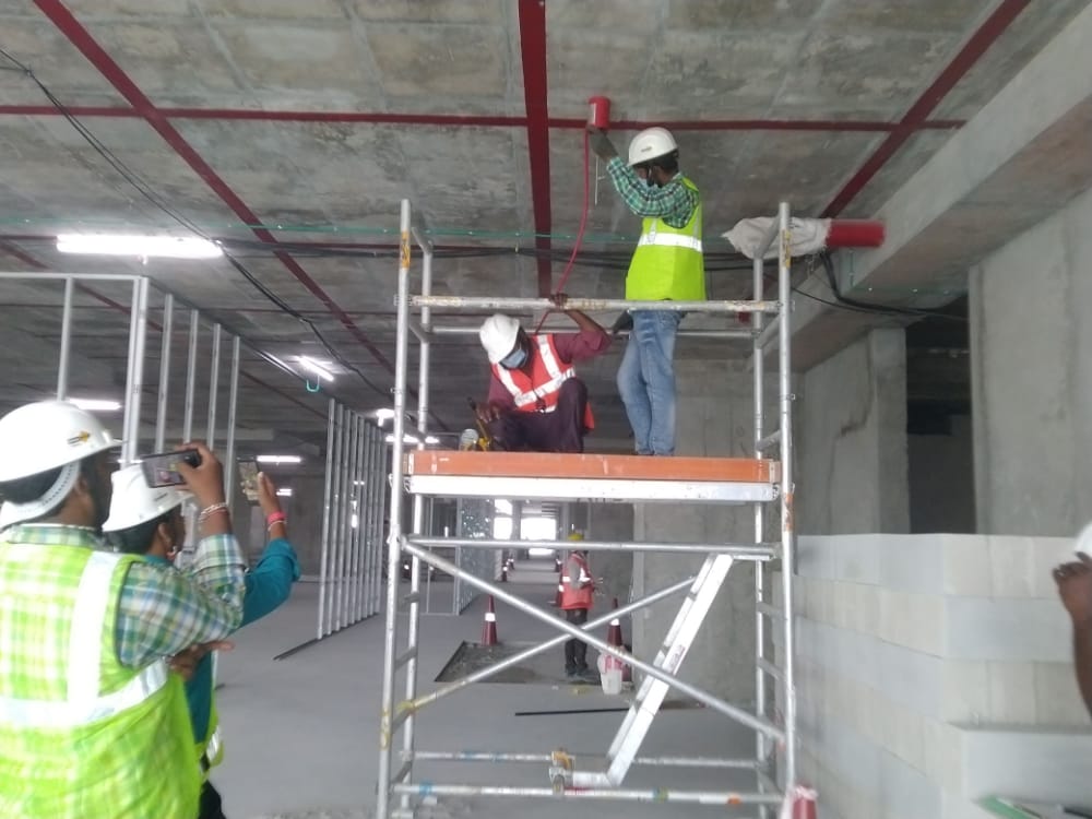
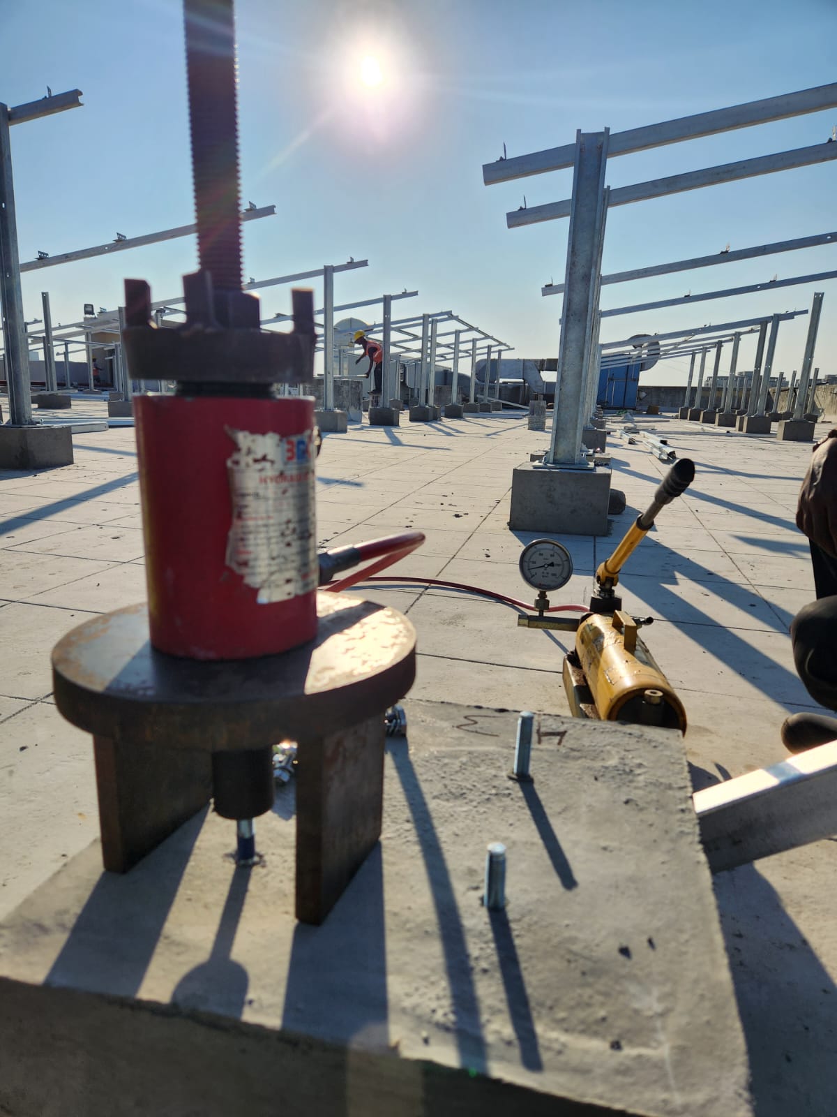
Anchor Bolt Pullout Test assembly on Parapet wall / Slab /High Rise Structures
Pull testing on Rock Anchor
Pullout Test Eye bolt Testing
Pullout Test on U Shape Hanging Hook
Pullout Test on Rope Hanging Hook
Parapet mounted MS hot dip galvanized bracket
Aluminium monorail with MS hot dip galvanized bracket
Pullout Test Procedure
- To carry out a proof test simply attach the hydraulic pull tester to the anchor and gradually turn the level, gradually increasing the load (to the manufacturers safe working load). If the anchor is flush-fixed (bolt head anchor or a frame fixing), it is not possible to test the anchor using this method.
- Normally performed to establish the load capacity strength of fixings that have been installed or fitted into walls, slabs, soffits etc, our pull out tests are vital for commercial buildings, railways, airports or domestic situations.
- There are many factors that can affect the strength and durability of eyebolts, anchor bolts, scaffold ties, stud anchors, resin bolts and safety wires, so it is vital that they are regularly checked tested and certified.
Pile Load Test Methodology
Objective
- As per IS: 2911-Part-4 2013 Clause No. 7.1.5 Pile Load Test by Pile Compression
Load Method, eRoutine Tst.
Methodology
- The pile bead should be shipped off to natural horizontal plane till sound concrete is met. The projecting reinforcement should be cut off or bent suitably and the top finished smooth and level with plaster of Paris or similar synthetic material where required. A bearing plate with a hole at the centre should be placed on the head of the pile for the jacks to rest.
Application of Load
- The test should be carried out by applying a series of vertical downward incremental load each increment being of about 20% of safe load on the pile. For testing of raker piles it is essential that loading is along the axis.
Reaction
- The reaction may be obtained from the following:
a. Kentledge placed on a platform supported clear of the test pile. In case of load test below under-pinned structure, the existing structure if having, adequate weight and suitable, construction may serve as kentledge. The centre of gravity of the kentledge should generally be
on the axis of the pile and the load applied by the jack should also be coaxial with this pile.
- Two-thirds of the final load at which the total displacement attains a value of 12 mm unless otherwise required in a given case on the basis of nature and type of structure in which case,
the safe load should be corresponding to the stated total displacement permissible.
Requirements
The safe load on single pile for the initial test should be least of the following:
- displacement attains a value of 12 mm unless otherwise required in a given case on the basis of nature and type of structure in which case,
the safe load should be corresponding to the stated total displacement permissible.
- 50% of the final load at which the total displacement equal 10% of the pile diameter in case
of uniform diameter piles and 7.5% of bulb diameter in case of under-reamed piles.
- Routine test shall be carried for a test load of at least one and half times the working load
and the maximum settlement of test loading in position being not exceeding 12 mm.
VERTICAL LOAD COMPRESSION TEST
LATERAL PILE LOAD TEST METHOD
Objective
As per I.S.: 2911 Part-4 -2013 Clause No.8.4 Pile Load Test by Pile Lateral Load
Method, Routine Test.
- The test is carried out by introducing a hydraulic jack with gauge between two piles or pile groups under test or the reaction may be suitably obtained otherwise. It may conduct by jack located between two piles or groups, the full load imposed by the jack shall be taken as the lateral resistance of each pile or group.
- The dial gauge shall be placed to measure the displacement of piles of 0.01 mm sensitivity spaced at 300mm one above the other. The dial gauge positioned at equal distance around the piles and normally held by datum bar resting on immovable supports. One dial gauge is placed diametrically opposite to the jack shall directly measure the displacement.
- Application of Load – The test should be carried out by applying a series of Lateral incremental load (20%) of estimated safe load on the pile. The applications of increment of test load and measurement of displacement in each stage of loading is maintained till displacement of the pile top is zero. 4. The Safe lateral load shall be taken as the least of the following (as per IS: 2911-Part- 4 2013 Clause No.7.4)
- Fifty percent of the final load at which the total displacement increases to 12mm
- Final load at which the displacement corresponds to 5mm
- Load corresponding to any other specified displacement as per
performance requirements.
METHODOLOGY
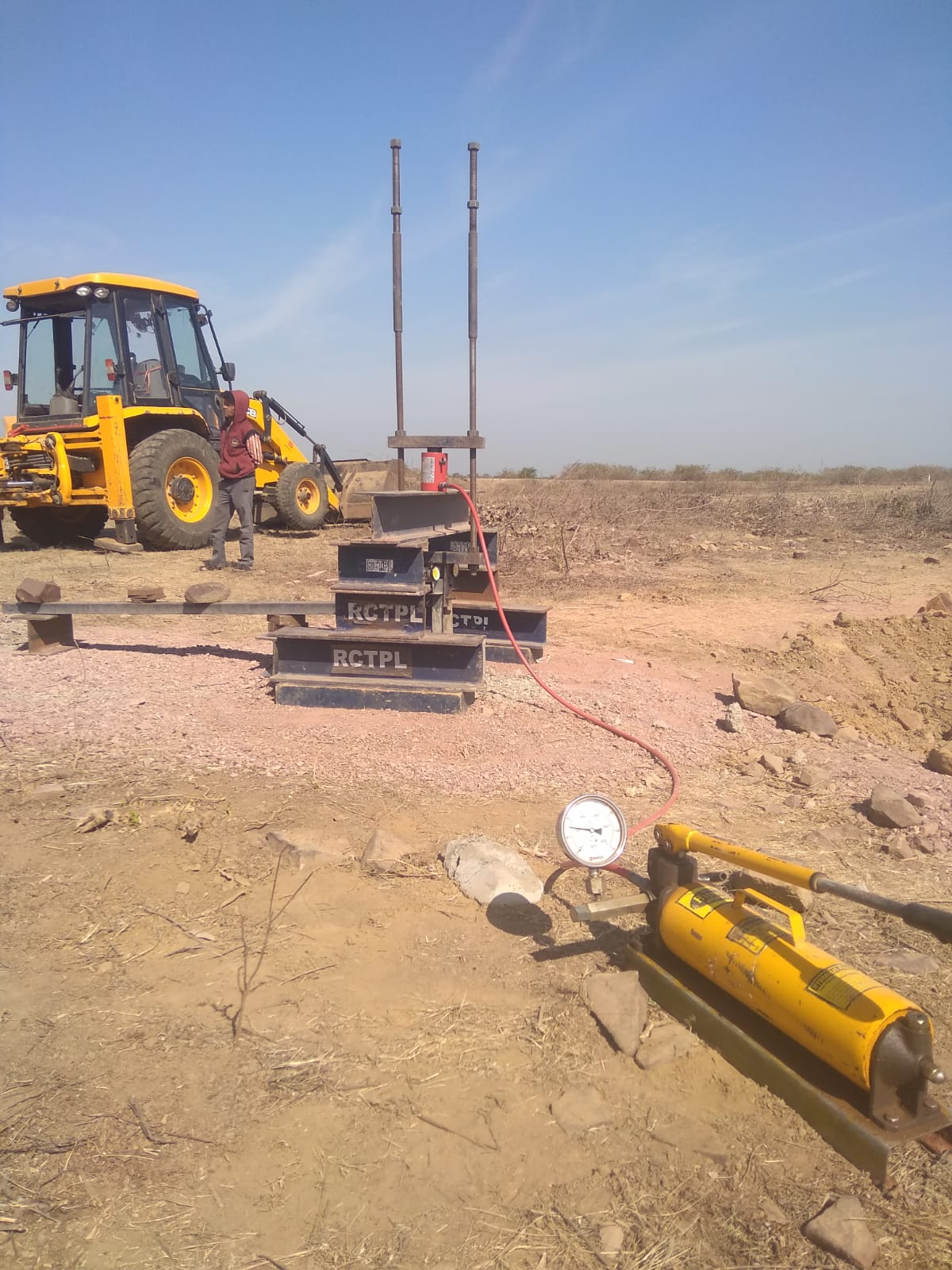
PULL OUT LOAD TEST METHOD
- The methodology adopted for Pile Load Test by Pull Out method is in such a way that the hydraulic jack is made to rest on rolled steel joist resting on two supports on the ground.
- The jack reacts against a frame attached to the top of the pile such that when the jack is operated, the pile gets pulled up and the reaction is transferred to the ground through the supports which are at least 2.5 D away from the test pile periphery (Where D is pile stem diameter of circular piles or diameter of the circumscribing circle in the case of square piles). The framework shall be capable of lifting the entire load through hydraulic jack.
- The dial gauge shall be placed to measure the displacement of piles of 0.01mm sensitivity. The dial gauge positioned at equal distance around the piles and normally held by datum bar resting on immovable supports.
- This test accurately predicts the foundation response at required full Pull Out design load. This method is applicable for both initial and routine test.
This test is also known as Uplift load test.
- . The framework can be attached to the pile top with the reinforcement bars (or Channel Section) which may be threaded or to which threaded bolts may be welded. It will have threads at top for fixing it to the framework. For larger loads the number of rods may have to be more and depending on the setup these may be put in a line or in any other symmetrical pattern.
- Application of Load – The test should be carried out by applying a series of uplift incremental load of safe load on the pile. The applications of increment of test load and measurement of displacement in each stage of loading is maintained till displacement of the pile top is zero. The test should be carried out by applying a series of incremental load (20%) of estimated safe load on the pile.
- The Safe load shall be taken as the least of the following (as per IS:2911- Part-4 2013 Clause No.9.4) a) Two-Third of the final load at which the total displacement attains a value of 12 mm or the load corresponding to a specified permissible uplift, and b) 50 Percent of the final load at which the load - displacement curve shows a clear break (downward trend). 8. The initial test shall be carried out up to twice the estimated safe load or
until the load displacement curve shows a clear- break (downward trend).
.jpg)


.jpg)
.jpg)
.jpg)